FADEC - Full Authority Digital Engine Control
FADEC is a system consisting of a digital computer and ancillary components that control an aircraft’s engine and propeller. First used in turbine-powered aircraft, and referred to as full authority digital electronic control, these sophisticated control systems are increasingly being used in piston powered aircraft.
In a spark-ignition reciprocating engine, the FADEC uses speed, temperature, and pressure sensors to monitor the status of each cylinder. A digital computer calculates the ideal pulse for each injector and adjusts ignition timing as necessary to achieve optimal performance. In a compression-ignition engine, the FADEC operates similarly and performs all of the same functions, excluding those specifically related to the spark ignition process.
FADEC systems eliminate the need for magnetos, carburetor heat, mixture controls, and engine priming. A single throttle lever is characteristic of an aircraft equipped with a FADEC system. The pilot simply positions the throttle lever to a desired detent, such as start, idle, cruise power, or max power, and the FADEC system adjusts the engine and propeller automatically for the mode selected. There is no need for the pilot to monitor or control the fuel-air mixture.
During aircraft starting, the FADEC primes the cylinders, adjusts the mixture, and positions the throttle based on engine temperature and ambient pressure. During cruise flight, the FADEC constantly monitors the engine and adjusts fuel flow and ignition timing individually in each cylinder. This precise control of the combustion process often results in decreased fuel consumption and increased horsepower.
FADEC systems are considered an essential part of the engine and propeller control and may be powered by the aircraft’s main electrical system. In many aircraft, FADEC uses power from a separate generator connected to the engine. In either case, there must be a backup electrical source available because failure of a FADEC system could result in a complete loss of engine thrust. To prevent loss of thrust, two separate and identical digital channels are incorporated for redundancy. Each channel is capable of providing all engine and propeller functions without limitations.
FADEC Fuel Control Systems
A full authority digital electronic control (FADEC) has been developed to control fuel flow on most new turbine engine models. A true FADEC system has no hydromechanical fuel control backup system. The system uses electronic sensors that feed engine parameter information into the EEC. The EEC gathers the needed information to determine the amount of fuel flow and transmits it to a fuel metering valve. The fuel metering valve simply reacts to the commands from the EEC. The EEC is a computer that is the computing section of the fuel delivery system and the metering valve meters the fuel flow. FADEC systems are used on many types of turbine engines from APUs to the largest propulsion engines.
FADEC for an Auxiliary Power Unit
An APU engine uses the aircraft fuel system to supply fuel to the fuel control. An electric boost pump may be used to supply fuel under pressure to the control. The fuel usually passes through an aircraft shutoff valve that is tied to the fire detecting/extinguishing system. An aircraft furnished in-line fuel filter may also be used. Fuel entering the fuel control unit first passes through a 10-micron filter. If the filter becomes contaminated, the resulting pressure drop opens the filter bypass valve and unfiltered fuel then is supplied to the APU. Shown in Figure is a pump with an inlet pressure access plug so that a fuel pressure gauge might be installed for troubleshooting purposes. Fuel then enters a positive displacement, gear-type pump. Upon discharge from the pump, the fuel passes through a 70-micron screen. The screen is installed at this point to filter any wear debris that might be discharged from the pump element. From the screen, fuel branches to the metering valve, differential pressure valve, and the ultimate relief valve. Also shown at this point is a pump discharge pressure access plug, another point where a pressure gauge might be installed.
The differential pressure valve maintains a constant pressure drop across the metering valve by bypassing fuel to the pump inlet so that metered flow is proportional to metering valve area. The metering valve area is modulated by the torque motor, which receives variable current from the ECU. The ultimate relief valve opens to bypass excess fuel back to the pump inlet whenever system pressure exceeds a predetermined pressure. This occurs during each shutdown since all flow is stopped by the shutoff valve and the differential pressure valve, is unable to bypass full pump capacity. Fuel flows from the metering valve out of the FCU, through the solenoid shutoff valve and on to the atomizer. Initial flow is through the primary nozzle tip only. The flow divider opens at higher pressure and adds flow through the secondary path.
FADEC Fuel Control Propulsion Engine
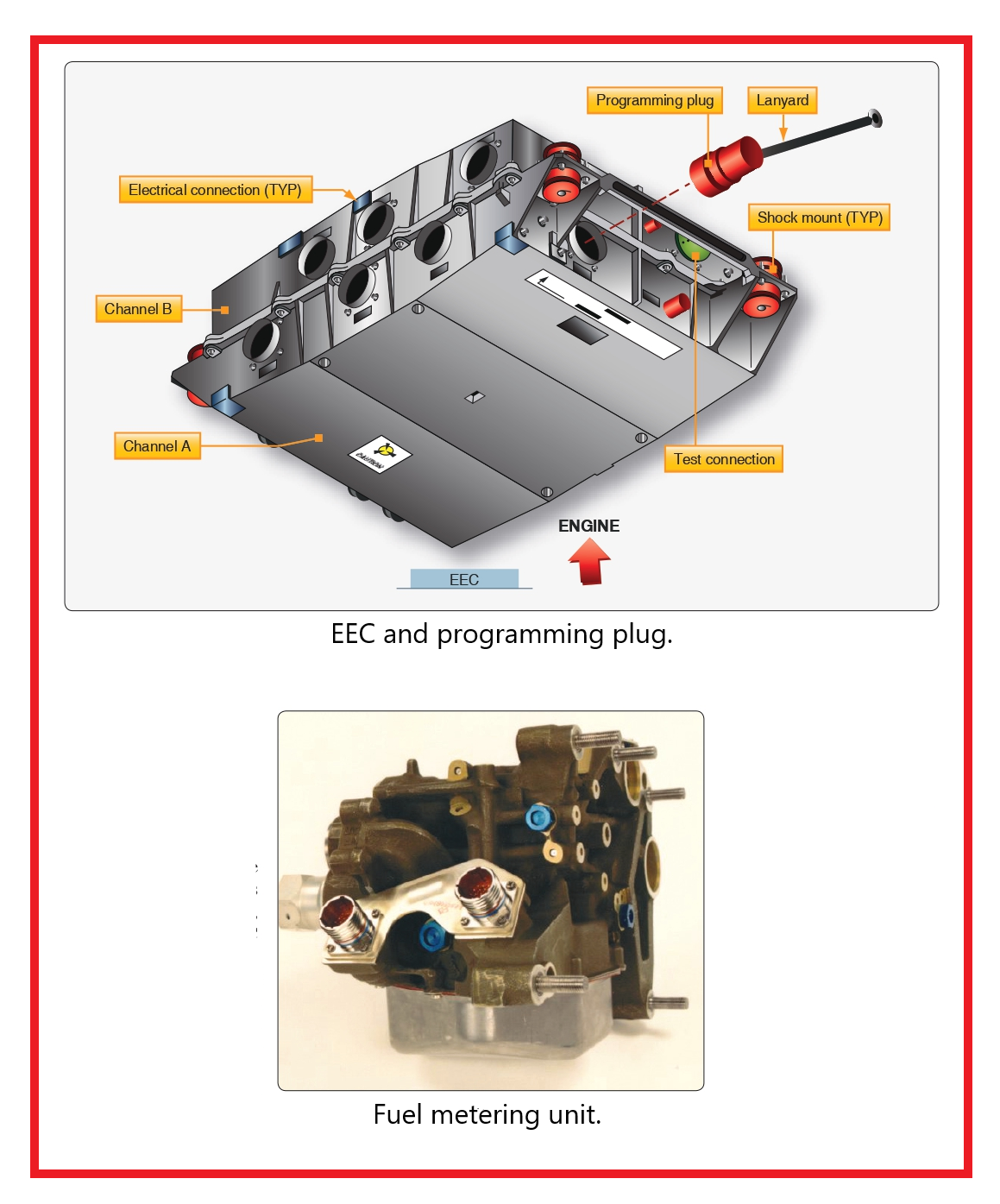
Many large high-bypass turbofan engines use the FADEC type of fuel control system. The EEC is the primary component of the FADEC engine fuel control system. The EEC is a computer that controls the operation of the engine. The EEC housing contains two electronic channels (two separate computers) that are physically separated internally and is naturally cooled by convection. The EEC is generally placed in an area of the engine nacelle that is cool during engine operation. It attaches to the lower-left fan case with shock mounts.
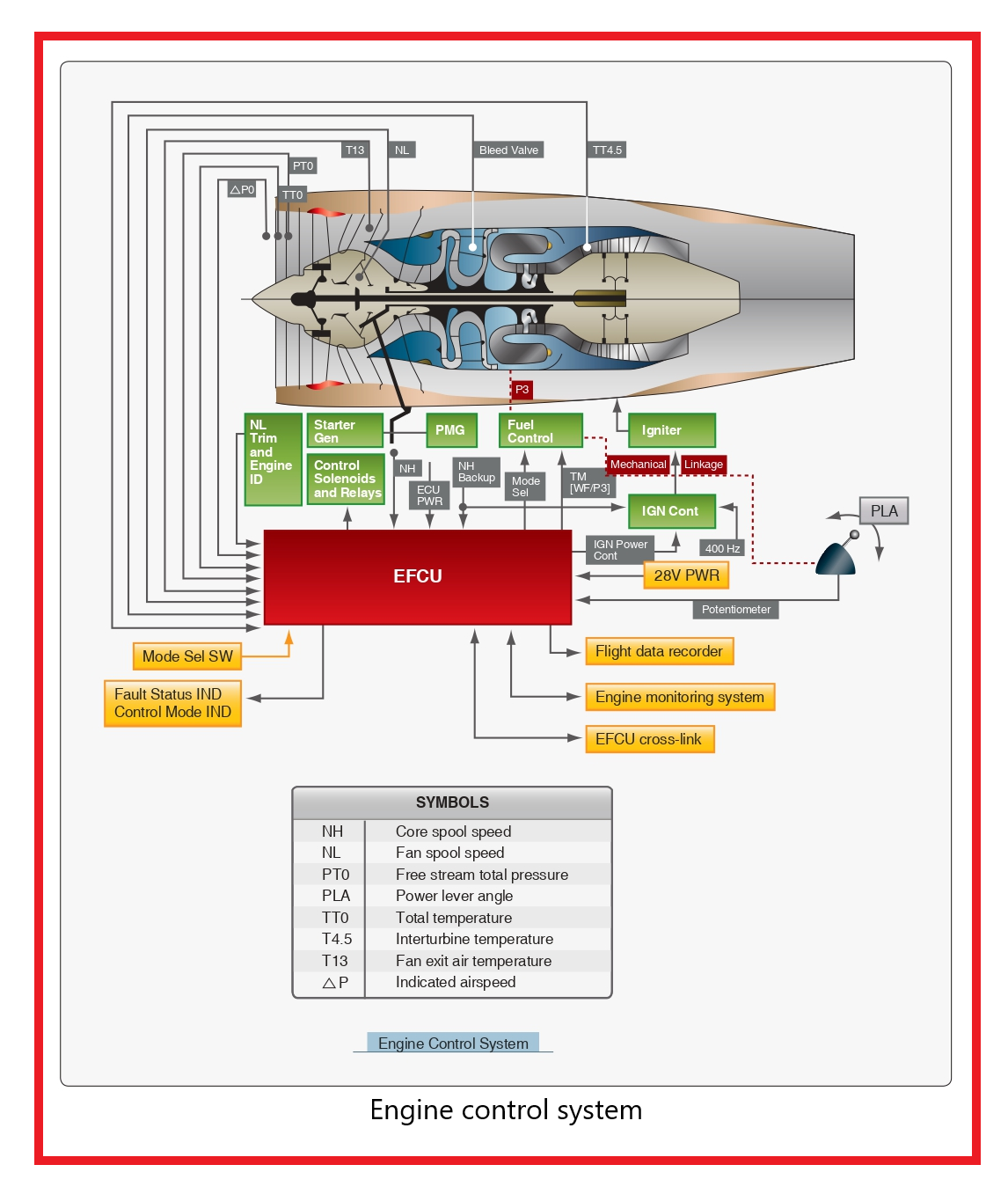
The EEC computer uses data it receives from many engine sensors and airplane systems to control the engine operation. It receives electronic signals from the flight deck to set engine power or thrust. The throttle lever angle resolver supplies the EEC with a signal in proportion to the thrust lever position. The EEC controls most engine components and receives feedback from them. Many components supply the EEC with data for engine operation.
Power for the EEC comes from the aircraft electrical system or the permanent magnet alternator (PMA). When the engine is running, the PMA supplies power to the EEC directly. The EEC is a two channel computer that controls every aspect of engine operation. Each channel, which is an independent computer, can completely control the operation of the engine. The processor does all of the control calculations and supplies all the data for the control signals for the torque motors and solenoids. The cross-talk logic compares data from channels A and B and uses the cross-talk logic to find which EEC channel is the best to control the output driver for a torque motor or solenoid bank. The primary channel controls all of the output drivers. If the cross-talk logic finds that the other channel is better for control of a specific bank, the EEC changes control of that one bank to the other channel. The EEC has output driver banks that supply the control signals to engine components. Each channel of the EEC supplies the driver banks with control signals. The EEC has both volatile and nonvolatile memory to store performance and maintenance data.
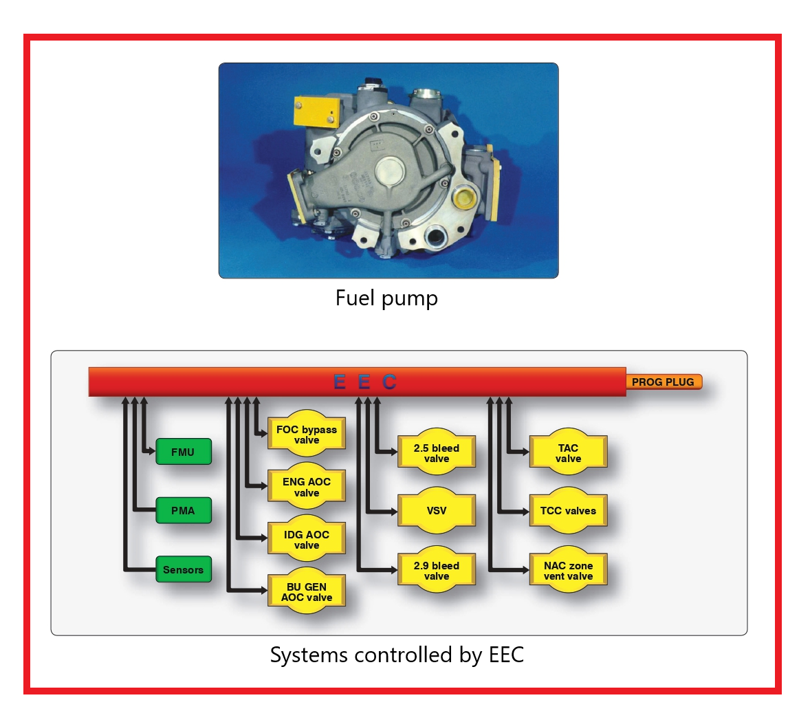
The EEC can control the engine thrust in two modes, which can be selected by use of a mode selection switch. In the normal mode, engine thrust is set with EPR; in the alternate mode, thrust is set by N1. When the fuel control switch is moved from run to cutoff, the EEC resets. During this reset, all fault data is recorded in the nonvolatile memory. The EEC controls the metering valve in the fuel metering unit to supply fuel flow for combustion. The fuel metering unit is mounted on the front face of the gearbox and is attached to the front of the fuel pump. The EEC also sends a signal to the minimum pressure and shutoff valve in the fuel metering unit to start or stop fuel flow. The EEC receives position feedback for several engine components by using rotary differential transformer, linear variable differential transformer, and thermocouples. These sensors feed engine parameter information from several systems back to the EEC. The fuel control run cutoff switch controls the high pressure fuel shut off valve that allows or cuts off fuel flow. The fuel temperature sensor thermocouple attaches to the fuel outlet line on the rear of the fuel/oil cooler and sends this information to the EEC. The EEC uses a torque motor driver to control the position of the metering valve in the fuel metering unit. The EEC uses solenoid drivers to control the other functions of the FMU. The EEC also controls several other subsystems of the engine, as shown in Figure, through torque motors and solenoids, such as fuel and air oil coolers, bleed valves, variable stator vanes, turbine cooling air valves, and the turbine case cooling system.
Each channel of the EEC has seven electrical connections, three on each side and one on the bottom. Both channels share the inputs of the two connections on the top of the EEC. These are the programming plug and test connector. The programming plug selects the proper software in the EEC for the thrust rating of the engine. The plug attaches to the engine fan case with a lanyard. When removing the EEC, the plug remains with the engine. Each channel of the EEC has three pneumatic connections on the bottom of the EEC. Transducers inside the EEC supply the related and opposite EEC channel with a signal in proportion to the pressure. The pressures that are read by the EEC are ambient pressure, burner pressure, LPC exit pressure, and fan inlet pressure. Each channel has its own wire color that connects the EEC to its sensors. Channel A wiring is blue and channel B sensor signals are green. The non-EEC circuit wire is gray while the thermocouple signals are yellow. This color coding helps simplify which sensors are used with each channel.
FADEC System Description
A FADEC is a solid-state digital electronic ignition and electronic sequential port fuel injection system with only one moving part that consists of the opening and closing of the fuel injector. FADEC continuously monitors and controls ignition, timing, and fuel mixture/delivery/injection, and spark ignition as an integrated control system. FADEC monitors engine operating conditions (crankshaft speed, top dead center position, the induction manifold pressure, and the induction air temperature) and then automatically adjusts the fuel-to-air ratio mixture and ignition timing accordingly for any given power setting to attain optimum engine performance. As a result, engines equipped with FADEC require neither magnetos nor manual mixture control.
This microprocessor-based system controls ignition timing for engine starting and varies timing with respect to engine speed and manifold pressure.
PowerLink provides control in both specified operating conditions and fault conditions. The system is designed to prevent adverse changes in power or thrust. In the event of loss of primary aircraft-supplied power, the engine controls continue to operate using a secondary power source (SPS). As a control device, the system performs self-diagnostics to determine overall system status and conveys this information to the pilot by various indicators on the health status annunciator (HSA) panel. PowerLink is able to withstand storage temperature extremes and operate at the same capacity as a non-FADEC-equipped engine in extreme heat, cold, and high humidity environments.
Low-Voltage Harness
The low-voltage harness connects all essential components of the FADEC System. This harness acts as a signal transfer bus interconnecting the electronic control units (ECUs) with aircraft power sources, the ignition switch, speed sensor assembly (SSA), temperature and pressure sensors. The fuel injector coils and all sensors, except the SSA and fuel pressure and manifold pressure sensors, are hardwired to the low-voltage harness. This harness transmits sensor inputs to the ECUs through a 50-pin connector. The harness connects to the engine-mounted pressure sensors via cannon plug connectors. The 25-jpin connectors connect the harness to the speed sensor signal conditioning unit. The low-voltage harness attaches to the cabin harness by a firewall-mounted data port through the same cabin harness/ bulkhead connector assembly. The bulkhead connectors also supply the aircraft electrical power required to run the system.
The ECU is at the heart of the system, providing both ignition and fuel injection control to operate the engine with the maximum efficiency realizable. Each ECU contains two microprocessors, referred to as a computer, that control two cylinders. Each computer controls its own assigned cylinder and is capable of providing redundant control for the other computer’s cylinder.
The computer constantly monitors the engine speed and timing pulses developed from the camshaft gear as they are detected by the SSA. Knowing the exact engine speed and the timing sequence of the engine, the computers monitor the manifold air pressure and manifold air temperature to calculate air density and determine the mass air flow into the cylinder during the intake stroke. The computers calculate the percentage of engine power based on engine revolutions per minute (rpm) and manifold air pressure.
From this information, the computer can then determine the fuel required for the combustion cycle for either best power or best economy mode of operation. The computer precisely times the injection event, and the duration of the injector should be on time for the correct fuel-to-air ratio. Then, the computer sets the spark ignition event and ignition timing, again based on percentage of power calculation. Exhaust gas temperature is measured after the burn to verify that the fuel-to-air ratio calculations were correct for that combustion event. This process is repeated by each computer for its own assigned cylinder on every combustion/power cycle.
The computers can also vary the amount of fuel to control the fuel-to-air ratio for each individual cylinder to control both cylinder head temperature (CHT) and exhaust gas temperature (EGT).
Electronic Control Unit (ECU)
An ECU is assigned to a pair of engine cylinders. The ECUs control the fuel mixture and spark timing for their respective engine cylinders; ECU 1 controls opposing cylinders 1 and 2, ECU 2 controls cylinders 3 and 4, and ECU 3 controls cylinders 5 and 6. Each ECU is divided into upper and lower portions. The lower portion contains an electronic circuit board, while the upper portion houses the ignition coils. Each electronic control board contains two independent microprocessor controllers that serve as control channels. During engine operation, one control channel is assigned to operate a single engine cylinder. Therefore, one ECU can control two engine cylinders, one control channel per cylinder. The control channels are independent, and there are no shared electronic components within one ECU. They also operate on independent and separate power supplies. However, if one control channel fails, the other control channel in the pair within the same ECU is capable of operating both its assigned cylinder and the other opposing engine cylinder as backup control for fuel injection and ignition timing. Each control channel on the ECU monitors the current operating conditions and operates its cylinder to attain engine operation within specified parameters. The following transmit inputs to the control channels across the low-voltage harness: 1. Speed sensor that monitors engine speed and crank position 2. Fuel pressure sensors 3. Manifold pressure sensors 4. Manifold air temperature (MAT) sensors 5. CHT sensors 6. EGT sensors.
All critical sensors are dually redundant with one sensor from each type of pair connected to control channels in different ECUs. Synthetic software default values are also used in the unlikely event that both sensors of a redundant pair fail. The control channel continuously monitors changes in engine speed, manifold pressure, manifold temperature, and fuel pressure based on sensor input relative to operating conditions to determine how much fuel to inject into the intake port of the cylinder.
PowerLink Ignition System
The ignition system consists of the high-voltage coils atop the ECU, the high-voltage harness, and spark plugs. Since there are two spark plugs per cylinder on all engines, a six-cylinder engine has 12 leads and 12 spark plugs. One end of each lead on the high-voltage harness attaches to a spark plug, and the other end of the lead wire attaches to the spark plug towers on each ECU. The spark tower pair is connected to opposite ends of one of the ECU’s coil packs. Two coil packs are located in the upper portion of the ECU. Each coil pack generates a high-voltage pulse for two spark plug towers. One tower fires a positive polarity pulse and the other of the same coil fires a negative polarity pulse. Each ECU controls the ignition spark for two engine cylinders. The control channel within each ECU commands one of the two coil packs to control the ignition spark for the engine cylinders. The high-voltage harness carries energy from the ECU spark towers to the spark plugs on the engine.
For both spark plugs in a given cylinder to fire on the compression stroke, both control channels must fire their coil packs. Each coil pack has a spark plug from each of the two cylinders controlled by that ECU unit.
The ignition spark is timed to the engine’s crankshaft position. The timing is variable throughout the engine’s operating range and is dependent upon the engine load conditions. The spark energy is also varied with respect to the engine load. NOTE: Engine ignition timing is established by the ECUs and cannot be manually adjusted.


